12
11/2026
Smart PDU Monitoring: Power-Only vs. Power + Environment
Compare power-only Smart PDU monitoring with a combined PDU and sensor setup: BM-CGQ04, 05, 06, 07 interfaces, coverage gaps and rack scoping guidance.
Smart PDU Monitoring: Power-Only vs. Power + Environment
A Smart Power Distribution Unit with metering answers one question very well: how much current each branch or socket is drawing, how much energy the rack has consumed, and whether a voltage or current limit has been crossed. It does not answer why the rack is warm, whether water is pooling under the floor, whether a cabinet door has been opened, or whether smoke is present. Those are separate measurements, and adding them changes the monitoring scope of the rack rather than the quality of the PDU.
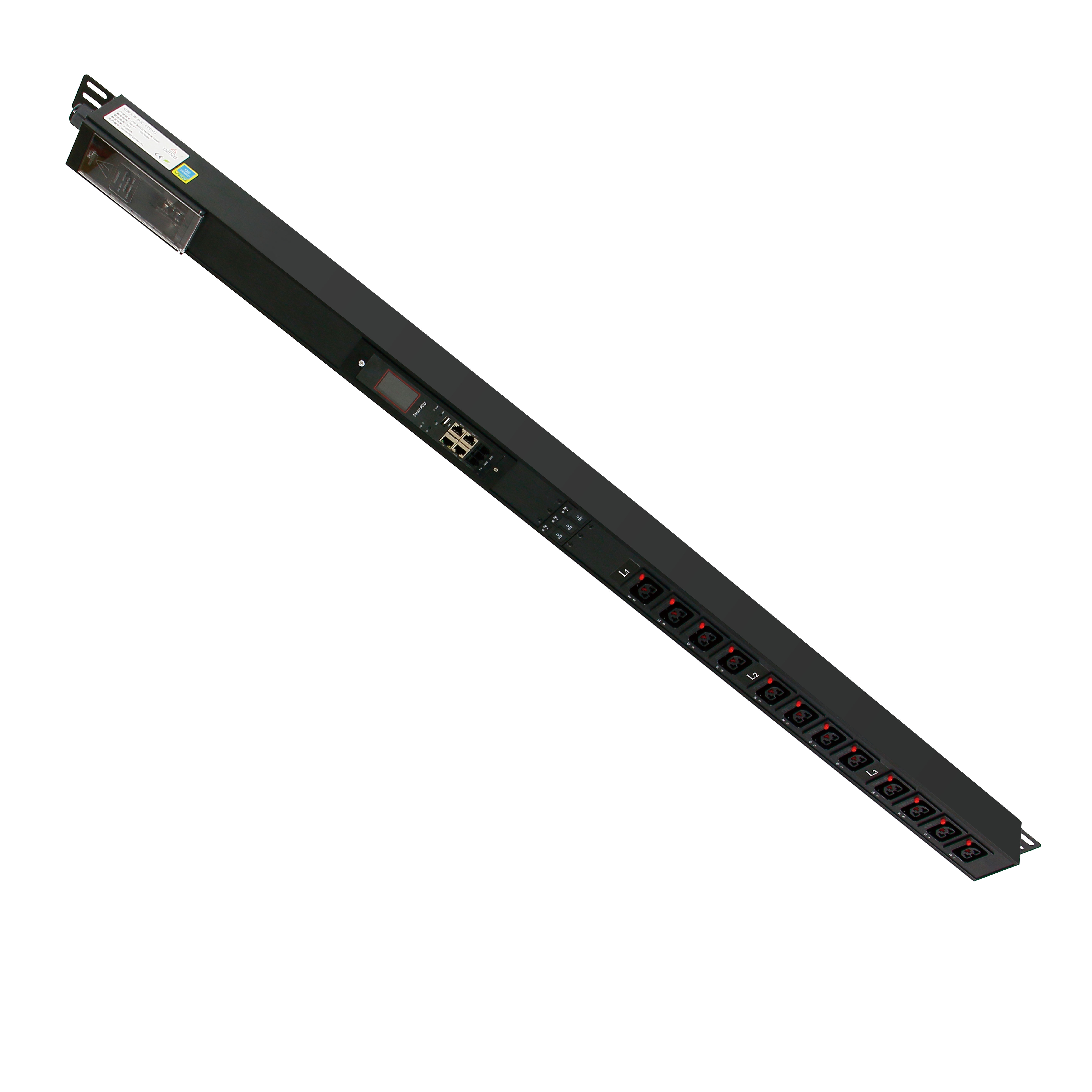
This comparison sets power-only monitoring against a combined power and environmental setup for data center and cloud racks. It uses the BOMPDU Intelligent 2nd generation PDU and 1U_1.5U 485 PDU families together with four BOMPDU sensors — the BM-CGQ07 door sensor, BM-CGQ06 water leak detector, BM-CGQ04 temperature and humidity sensor and BM-CGQ05 smoke detector — and maps each device to the interface it actually has, because RS-485 Modbus connects part of this list and not all of it.
Power-only monitoring: the scope a Smart PDU covers
A network managed PDU with metering is a power instrument. The BOMPDU Intelligent 2nd generation PDU is specified for an AC 110–250 V, 50/60 Hz input with a maximum load current of 0–63 A, in single-phase or three-phase input configurations. Its input measurement set covers current, voltage, electrical energy and power — active, reactive and apparent power plus power factor — with stated input accuracy of 0.5% for voltage across 85–250 V, accuracy level 1 for current between 0.65 A and 3.1 A, and accuracy level 0.5 between 3.1 A and 63 A.
The output side is where socket-level monitoring becomes a design decision rather than a label. Each output is monitored and controlled separately, with a rated output current of 16 A per channel and 32 A per board. Output accuracy is stated as 1% for voltage across 85–250 V, with current monitoring from 0.2 A to 16 A at 2% between 0.2 A and 0.8 A and 1% between 0.8 A and 16 A. The auxiliary module carries four outputs and the main module supports up to eight auxiliary modules, so outlet density is a question of module count rather than a fixed configuration.
The 1U_1.5U 485 PDU delivers the same monitoring idea in a smaller form factor: 100–240 V rated input across a 90–264 V range, level 1 (1% ± 0.1) accuracy for voltage, current, power and energy, 0.01 resolution on the segment-code LCD, and overvoltage, undervoltage and overcurrent alarms with settable parameters. Both families communicate over RS485 using the Modbus protocol, which makes them readable by the same polling system.
Read together, these specifications define the visible layer of a power-only deployment: branch current, energy, threshold alarms and remote control of outputs. Every value describes electricity. None of them describes the room the rack sits in.

What power-only monitoring leaves invisible
Four conditions that commonly affect a rack sit outside the measurement set of any metering PDU: air temperature and humidity at the inlet, the presence of liquid, the physical state of the cabinet door, and smoke. A power-only Smart PDU can show a load increase, but it cannot distinguish a newly installed server from a failing fan. It can show a branch current falling to zero, but not that a cabinet door was opened shortly before the drop.
The difference becomes concrete at the alarm stage rather than the dashboard stage. A current threshold alarm reports that the electrical state changed. An environmental reading explains why the electrical state may be about to change. Combining both layers turns a single-point alert into a sequence that can be diagnosed without sending someone to the aisle to look.
The four sensors and the interface each one actually uses
The sensor list in this comparison is not one protocol family. Each device has its own output type, and that output type decides where the device connects and what else has to be purchased to read it.
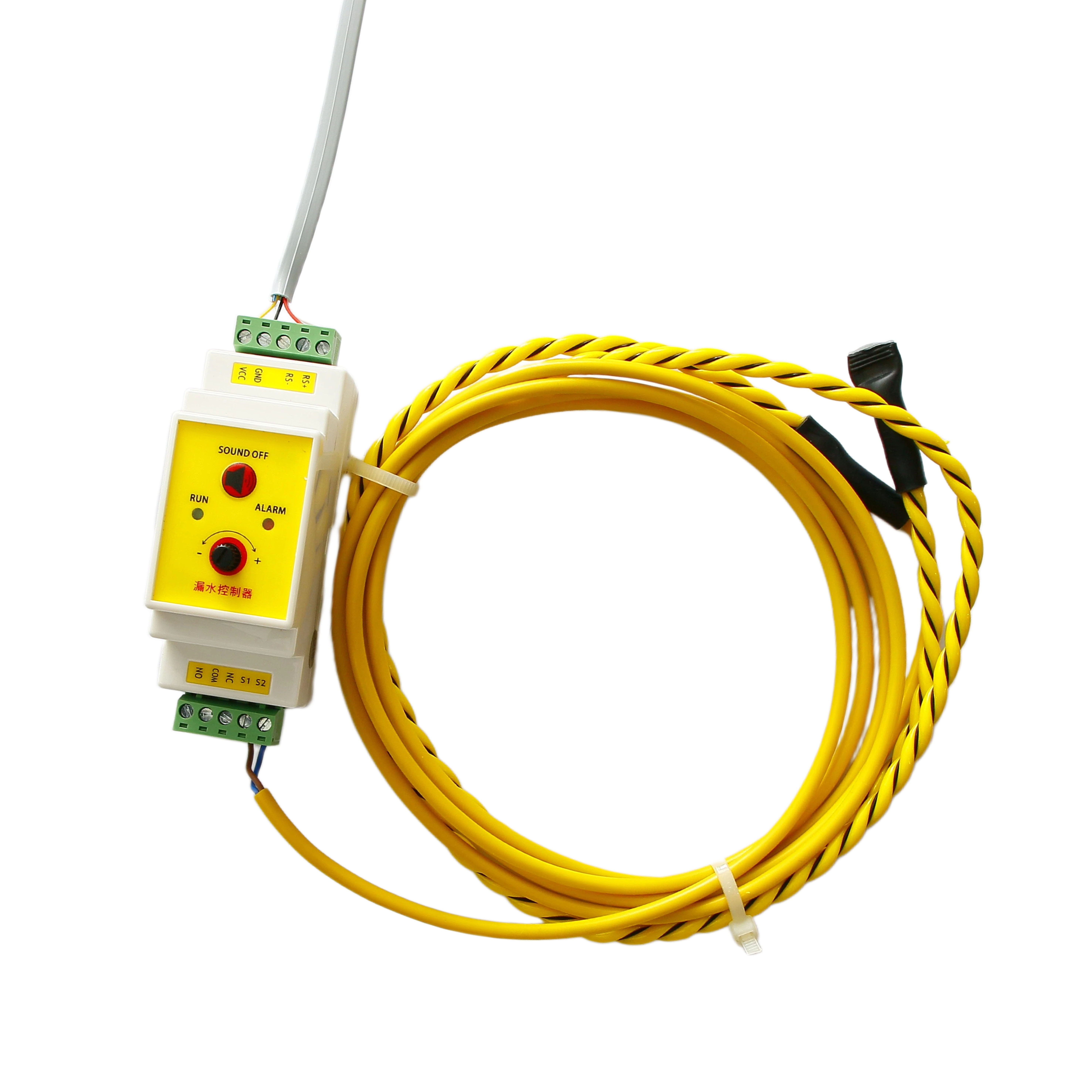
BM-CGQ06 water leak detector: the RS-485 Modbus node
The BM-CGQ06 is the only device in this group that is itself an RS-485 Modbus node. It is a leak detection controller in a white PVC housing, operating on 12 V DC at 3 W, mounted on a 35 mm DIN rail, with dimensions of 108 × 59 × 37 mm (88 × 59 × 37 mm excluding terminals) and a net weight of 150 g. It supports a maximum sensor cable length of 500 m and RS-485 communication up to 1200 m without a repeater, and it is specified for −25 °C to 50 °C and 5%–90% RH non-condensing. Two LEDs indicate power and communication status, the relay output is SPDT with normally open or normally closed options, and the unit is RoHS certified with an industrial-grade protection level and a stated accuracy rating of 100%.
BM-CGQ07 door sensor: a dry contact, not a bus device
The BM-CGQ07 is a dry contact sensor with a configurable normally open or normally closed contact, a 2-wire terminal output and an operating voltage of 5–30 V DC. Its actuation gap is ≤ 15 mm, its protection rating is IP40, it operates from −10 °C to +55 °C, and it is supplied with a 1 m cable as standard, with custom lengths available. The housing is ABS with an embedded permanent magnet. It produces a contact state; it does not produce a Modbus register on its own.
The 1 m standard cable is a practical constraint rather than a detail. It sets how far the sensor can sit from whatever reads the contact, which is why custom cable length belongs in the specification instead of in a post-installation change order.

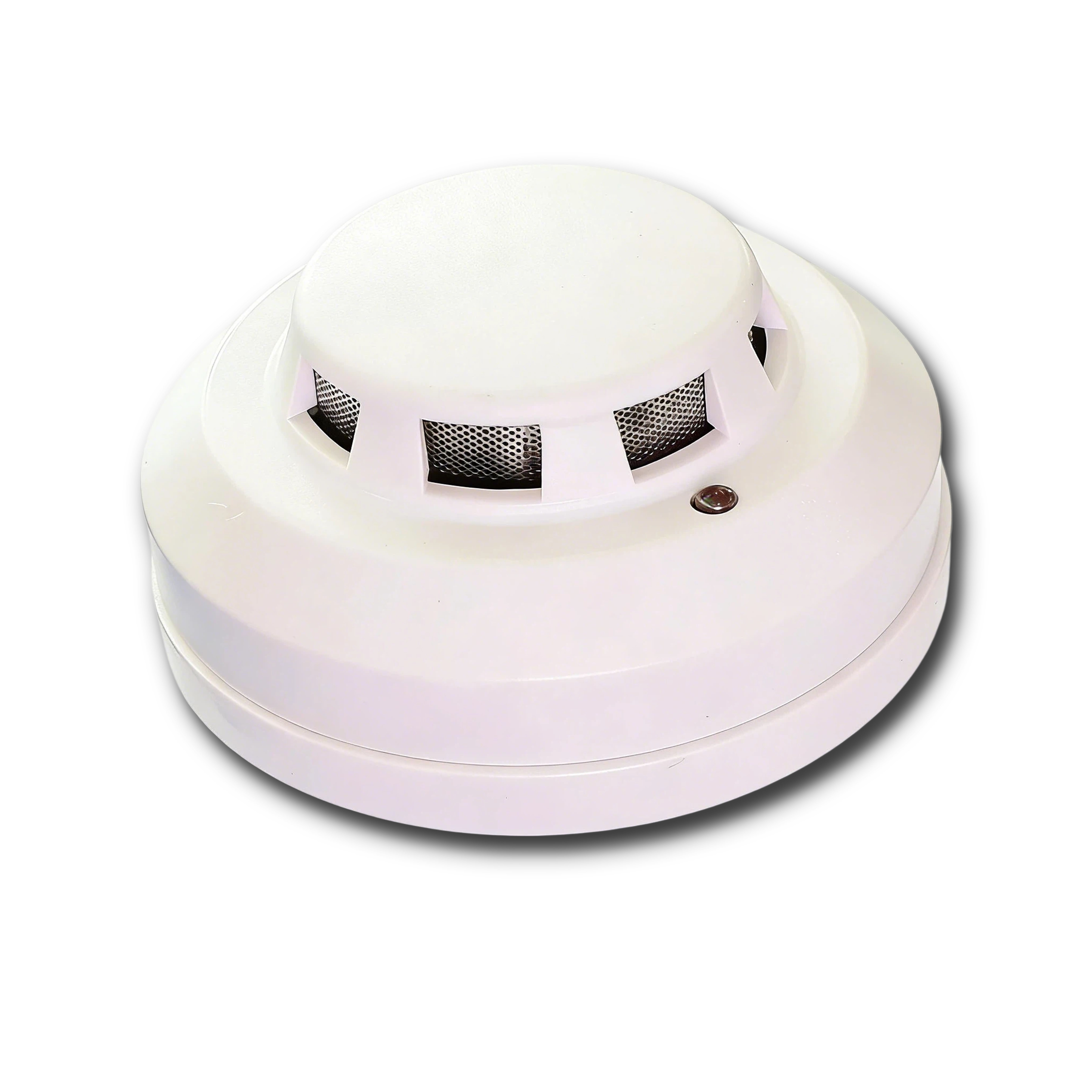
BM-CGQ05 smoke detector: an alarm output on 2-wire or 4-wire wiring
The BM-CGQ05 is a wired photoelectric smoke detector in an ABS housing, powered from 10–35 V DC, with an LED alarm indicator, wall or ceiling mounting on a standard base, and either 2-wire or 4-wire wiring configuration. It provides an alarm signal output and is described as meeting an industrial-grade application standard. It is a detection device: the alarm output is a signal to a supervising system, and the product documentation does not describe suppression, extinguishing or addressable loop functions.
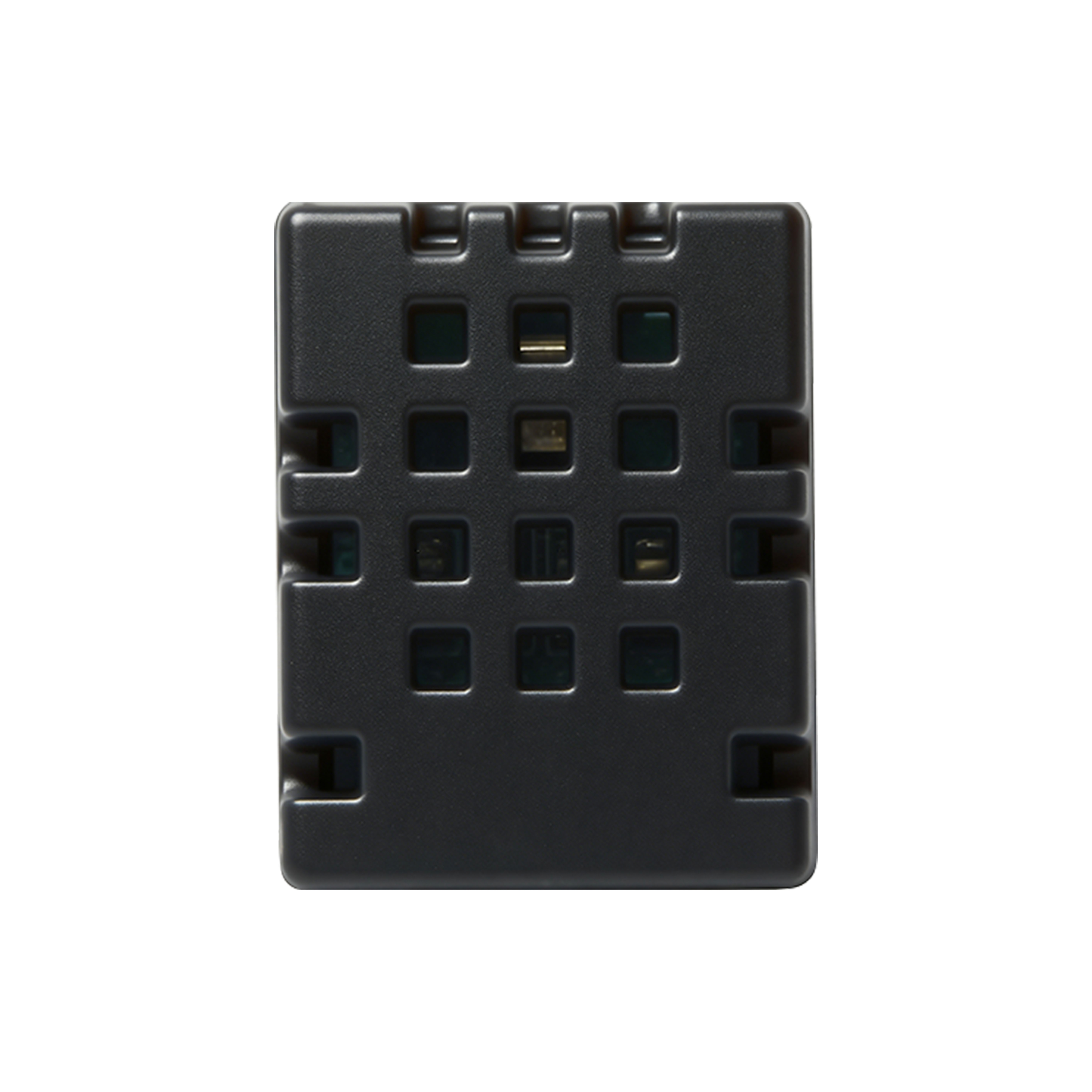
BM-CGQ04 temperature and humidity sensor: an I²C component
The BM-CGQ04 is a digital temperature and humidity sensor built from a semiconductor silicon-based capacitive humidity element with an on-chip temperature sensor. It runs from 2.2–5.5 V DC with a 250 nA sleep current and 980 µA measuring current, covers 0–100 %RH at ±3 %RH typical and −40 °C to 80 °C at ±0.5 °C typical (both at 25 °C, 3.3 V), is fully calibrated at the factory, and carries JEDEC JESD22-A114 ESD protection at HBM ±4 kV. It is supplied as an SMD part at 50 pieces per tray, roughly 0.9 g per sensor, with an I²C interface.
The SMD form factor is the most important planning fact about this device. A rack-inlet temperature and humidity reading requires the part to be mounted in a probe or enclosure and connected to an I²C host; it is not a DIN-rail instrument with a terminal block. Buyers who assume otherwise will receive a component where they expected a sensor.
RS-485 Modbus as the shared thread — and the three points where it stops
RS-485 Modbus carries power telemetry from both BOMPDU PDU families and leak status from the BM-CGQ06, and the two can share a bus segment: the PDU uses RS485 with Modbus protocol, and the leak detector uses RS-485 with MODBUS at up to 1200 m without a repeater. For a rack-level deployment this is the most economical arrangement, because one poll returns both electrical and water-detection data, and the leak detector's SPDT relay adds a hardwired interlock path that does not depend on the bus at all.
The thread stops at the other three devices, and it is better to plan for that than to discover it during commissioning:
- Door state. A configurable dry contact on a 2-wire terminal has to land on a digital input. The published Intelligent 2nd generation PDU specification describes RS485/Modbus communication, a segment-code LCD and overvoltage, undervoltage and overcurrent alarms with settable parameters; it does not describe dry-contact input terminals, so the input path should be confirmed at model level rather than assumed.
- Smoke alarm. The BM-CGQ05 delivers an alarm signal output over 2-wire or 4-wire wiring. That signal needs an alarm input on a controller or a panel interface, which sits outside the PDU's documented interface set.
- Temperature and humidity. I²C is a board-level bus. It requires an I²C host and a probe assembly, a different integration task from terminating an RS-485 pair.
Practical consequence: a combined power and environmental deployment usually contains one RS-485 segment, a small number of discrete inputs and one I²C channel. The controller that supplies those inputs is a separate line in the design — and in the budget — from the PDU itself.
Monitoring coverage, side by side
The first table maps each device to its signal and interface, which is the part of the comparison that decides cable, ports and cost. The second table compares what a rack can actually report in each configuration.
| Device | Signal produced | Interface | Integration requirement |
|---|---|---|---|
| Intelligent 2nd generation PDU | Input and output current, voltage, energy, active/reactive/apparent power, power factor; overvoltage, undervoltage and overcurrent alarms | RS485 / Modbus | RS-485 polling system |
| 1U_1.5U 485 PDU | Voltage, current, power and energy at level 1 (1% ± 0.1); settable alarms | RS485 / Modbus | RS-485 polling system |
| BM-CGQ06 water leak detector | Leak status; SPDT relay | RS-485 / MODBUS; relay contact | RS-485 segment; optional hardwired interlock |
| BM-CGQ07 door sensor | Contact open or closed | Dry contact, NO/NC, 2-wire, 5–30 V DC | Digital input on a host controller |
| BM-CGQ05 smoke detector | Alarm signal | 2-wire or 4-wire alarm output | Alarm input or panel interface |
| BM-CGQ04 temperature and humidity sensor | Temperature and relative humidity | I²C, 2.2–5.5 V DC | I²C host plus probe or enclosure mounting |
| What the rack needs to report | Power-only Smart PDU | Smart PDU + environmental sensors |
|---|---|---|
| Current per output | Measured, 0.2–16 A range, 1%/2% accuracy bands | Unchanged |
| Energy and power | Measured; active, reactive, apparent power and power factor on the 2nd generation unit | Unchanged |
| Overvoltage, undervoltage, overcurrent | Settable alarm parameters | Unchanged |
| Remote on/off per output | Separate monitoring and control | Unchanged |
| Inlet temperature and humidity | Not part of the PDU measurement set | BM-CGQ04, ±0.5 °C and ±3 %RH typical |
| Liquid under floor or inside cabinet | Not part of the PDU measurement set | BM-CGQ06, up to 500 m sensing cable |
| Cabinet door state | Not part of the PDU measurement set | BM-CGQ07, ≤ 15 mm actuation gap |
| Smoke | Not part of the PDU measurement set | BM-CGQ05 photoelectric detection |
| Communication footprint | One RS-485 segment | One RS-485 segment plus discrete inputs and one I²C channel |
Both tables reflect published specifications. Environmental parameters are not listed as PDU measurement inputs, which means they have to be sourced from a separate device rather than assumed to be latent in the PDU.
Reading the second table as a buyer: the left column is enough when the risk you are managing is electrical — overload, unbalanced loading, an unexplained energy increase, or an outlet that needs a remote restart. The right column becomes the better fit when rack failures in your environment tend to arrive from outside the electrical circuit: a warm inlet after a cooling change, water from a nearby chilled-water line, a door left open during service, or a smoke event in an enclosed cabinet.
Limits of an environmental overlay
Adding sensors does not raise the electrical capability of the rack. The Intelligent 2nd generation PDU remains limited to its stated output ratings — 16 A per channel, 32 A per board and 0–63 A maximum load current — and the 1U/1.5U family remains a metering and alarm device with level 1 accuracy. Environmental monitoring adds observations, not capacity, redundancy or switching authority.
Detection is also not containment. The BM-CGQ05 reports smoke through an alarm output; it is not a suppression system and the documentation does not describe extinguishing functions. The BM-CGQ06 relay can signal a leak and drive an interlock, but it does not close a valve by itself. The BM-CGQ07 reports a door contact; it is not a credential-based access control system and does not decide who may open the cabinet.
Three further boundaries are worth stating before a purchase order:
- Measurement points, not zones. One temperature sensor reports the air where it is mounted. One door contact reports one door. Coverage is a function of placement, and the 1 m standard cable on the door sensor constrains it.
- Alarm delivery depends on the supervising layer. With RS-485 Modbus, environmental and power data are only as available as the polling master. As an external reference point, Raritan states that its intelligent rack PDUs can send alerts via SNMP, email and syslog when predefined power or environmental thresholds are exceeded — which shows that multi-channel alert transport is a platform function rather than a property of any single sensor.
- Protocol requirements must be resolved at system level. BOMPDU's data center application description lists SNMP, over-current protection and remote reset as site requirements, while the PDU specification documents RS485/Modbus and overcurrent alarms with settable parameters. Where a site depends on SNMP supervision, that requirement has to be answered by the monitoring platform, not assumed to be native to the PDU.
Scoping: how many sensors and where they go
Scoping the overlay is a short exercise once the interfaces are known, because each device type carries its own physical limits.
- Temperature and humidity. Start with one BM-CGQ04 position per rack at the inlet, since inlet air is what the equipment actually draws. The part is an SMD device, so each position implies a probe or enclosure and an I²C connection back to a host.
- Door state. One BM-CGQ07 per door that is routinely opened for service. Confirm cable length at order time: the 1 m standard is often enough for a front door and short for a rear door routed through a cable manager.
- Leak detection. The BM-CGQ06 is a zone device rather than a rack device: its 500 m maximum sensing cable and 1200 m RS-485 range allow one controller to serve a row or a room, with the 35 mm DIN rail mounted in a panel or cabinet.
- Smoke. The BM-CGQ05 mounts on a wall or ceiling base, so it belongs to the enclosed space around the racks rather than to a specific rack unit.
Step-by-step: validating the upgrade on one rack
A single rack is enough to prove a combined power and environmental design before it is repeated across a row.
- List the signals, not the products. Write down what the rack must report, then map each signal to an interface using the first table. Signals without an interface are the ones that will stop the project.
- Confirm termination in writing. Ask specifically how the door contact, the smoke alarm output and the I²C sensor will be read on this rack. The PDU documentation covers RS485/Modbus and settable alarms; the rest needs a named host input.
- Set and record thresholds. The PDU alarm parameters are settable, so record the overvoltage, undervoltage and overcurrent set points alongside the environmental limits you intend to enforce. Choose the leak detector relay state — normally open or normally closed — deliberately rather than by default.
- Test each alarm path end to end. Trigger the contact, the leak relay and the smoke output at the device and confirm the alarm arrives at the person who acts on it, not just at the controller.
- Record the physical layout. Note RS-485 addresses, DIN rail position, and the cable length actually used against the 1 m door cable, 500 m sensing cable and 1200 m RS-485 limits.
- Extend only after the first rack is stable. Repeating a validated layout is faster than diagnosing three racks at once.
Data center and cloud rack context, and where BOMPDU fits
BOMPDU's data center application description is written around 24/7 continuous operation under stable server power, with servers, switches, UPS and environment monitoring units as supporting equipment, and with remote power control, energy consumption monitoring and remote reset as the PDU functions. That description already names an environment monitoring unit as part of the rack — the sensor layer discussed here is that unit, made specific.
For edge and telecom cabinets, the same logic applies with different emphasis: the documented telecom scenario calls for remote reboot plus voltage and current monitoring, with wide temperature range and lightning protection as site requirements. Remote reboot stays a PDU function; the door and leak contacts answer the question of who was at the cabinet and whether water reached it, which a power alarm cannot.
BOMPDU — Wuxi Bom Electronic Technology Co., Ltd. — was established in 2018 and works on end-of-row power distribution solutions for data centers. Its manufacturing facility covers 5000 m², employs approximately 70 staff and has an annual production capacity of 10000 units, with an R&D team of 12 engineers and more than ten invention patents for PDU products. The production facility has fully complied with ISO 9000 and ISO 14000 standards. Main markets are the USA, SEA, EU and ME. The product range relevant to this comparison includes the Intelligent 2nd generation PDU, the 1U_1.5U 485 PDU, and the BM-CGQ04, BM-CGQ05, BM-CGQ06 and BM-CGQ07 sensor devices.
FAQ
Do the Smart PDU and the environmental sensors share one communication bus?
Partly. Both BOMPDU PDU families communicate over RS485 with Modbus protocol, and the BM-CGQ06 water leak detector is itself an RS-485 MODBUS device with a communication range up to 1200 m without a repeater, so power data and leak status can travel on one segment. The other three devices do not join that bus directly: the BM-CGQ07 provides a configurable dry contact over a 2-wire terminal at 5–30 V DC, the BM-CGQ05 provides an alarm signal output over 2-wire or 4-wire wiring, and the BM-CGQ04 is an I²C device running from 2.2–5.5 V DC. Those three need a host that supplies a digital input, an alarm input and an I²C port.
Which sensor should be added first to a data center rack?
Choose by the failure mode you are trying to shorten, not by product category. If rack faults in your site follow cooling changes or airflow problems, begin with the BM-CGQ04 at the inlet, since ±0.5 °C and ±3 %RH typical accuracy at 25 °C and 3.3 V is sufficient to trend a rack position. If the room has chilled-water piping, condensate lines or an overhead water path, begin with the BM-CGQ06, whose 500 m sensing cable allows one controller to cover a row. If after-hours access or an unexplained load change dominates, begin with the BM-CGQ07 door contact. In enclosed cabinets where early warning is the priority, the BM-CGQ05 photoelectric detector addresses that scenario.
What changes in the bill of materials when sensors are added?
Three line items appear that a power-only rack does not carry. First, the sensor devices themselves: one BM-CGQ06 DIN-rail controller per zone, one BM-CGQ07 per door, one BM-CGQ05 per enclosed space and one BM-CGQ04 per measurement position. Second, physical mounting: a probe or enclosure for the SMD temperature sensor, a 35 mm DIN rail position for the leak controller, and standard bases for the smoke detector. Third, integration hardware: a host controller with discrete inputs, an alarm input and an I²C channel, plus cabling within the 1 m door-sensor standard or the 500 m leak sensing limit. Published BOMPDU material does not list unit prices, MOQ or lead time, so those items require a quotation rather than an estimate.
How can a pilot rack validate the design before a full rollout?
Instrument one rack, then test the alarm path rather than the readings. Set and record the PDU's overvoltage, undervoltage and overcurrent thresholds, select the leak detector relay state deliberately, and confirm the door contact, leak relay and smoke output each reach the person who acts on the alarm. Record cabling against the documented limits — 1 m standard door cable, 500 m maximum leak sensing cable and 1200 m RS-485 range — so the layout can be repeated without recalculation. A pilot that only displays values in a dashboard has not yet validated the design.
How should the sensor layer be specified in an RFQ?
Specify per device, not per category. State the model, the interface and the integration path for each item: RS485/Modbus for the PDU and the BM-CGQ06, a 5–30 V DC digital input for the BM-CGQ07 contact, an alarm input for the BM-CGQ05 output, and an I²C host for the BM-CGQ04. Add the mounting assumption, the required cable length and who supplies the host controller. Where the supervising system is IP-based, list protocol support as its own line rather than assuming it. The BOMPDU product brochure, available at this download link, can be used as the starting reference for model names and parameters, and the team can be reached through www.wuxibom.com or by email at tony1091803@wxbom.cn for a configuration review of a specific rack.
Conclusion
A power-only Smart PDU is a complete instrument for the electrical layer: it measures current, voltage, energy and power at input and output, applies settable overvoltage, undervoltage and overcurrent alarms, and allows separate monitoring and control of each output over RS485 Modbus. It is the correct choice when the risk being managed is load, energy or remote restart, and when the surrounding room is monitored by other means.
A combined power and environmental setup adds four observations the PDU does not produce: inlet temperature and humidity from the BM-CGQ04, liquid presence from the BM-CGQ06, door state from the BM-CGQ07 and smoke from the BM-CGQ05. The integration is not uniform — one RS-485 Modbus segment covers the PDU and the leak detector, while the door contact, smoke output and I²C sensor each need their own host input. Planning for that asymmetry at specification stage is what separates a working combined deployment from a rack full of devices that report to nothing.
Next step: if you are scoping a combined power and environmental layout for a data center or cloud rack, the BOMPDU product brochure covers the PDU and sensor model parameters in one document. Download it here: BOMPDU product brochure (PDF). Configuration questions can go to tony1091803@wxbom.cn or +86 18751550927.